Automated Optical Inspection System
TI-GTI
Techno Horizon has responded to the diverse needs of our customers over the years and accumulated this know-how in our latest 3D AOI. TI-GTI solves your challenges in the component placement process with industry-leading inspection performance.
Features
3D AOI provides you the “outstanding solder fillet inspection performance”. TI-GTI helps you to improve the quality of your products, and can be utilized to appeal to your clients as “proof of reliable solder fillet inspection”.
TI-GTI not only serves as an inspection system to stop the outflow of defective products, but also enables easy numerical management and analysis of trends such as component mounting positions. You can construct your production lines with higher yields by utilizing this information.
01 Hardware Features

Fast and accurate object form reproduction
TI-GTI equipped with a 4-way phase-shift 3D illumination system capable of measuring a range of -5 to +20mm in the height direction with a resolution of 1um (variation of 3σ +/-15µm*). This allows the system to captures minute changes in height direction.
The system is equipped with epi-illumination (Top R illumination) and large aperture 300mm circular illumination (Bottom RGB illumination) as 2D illumination system to capture minute luminance changes. The performance of character inspection, etc. has been dramatically improved.
*On our evaluation board

Efficient acquisition of 3D and 2D images over a wide area
The vertical camera is equipped with a 125mm diameter telecentric lens with anti-seismic measures. It has the industry’s largest field of view of 67.5 mm x 67.5 mm, enabling efficient imaging of a wide area.
The 4-way oblique camera unit* enables reliable imaging and inspection of areas that cannot be imaged vertically.
*Factory option

Automatic backup mechanism
The system is equipped with backup pins that push up both ends of the board in the width direction from below, enabling inspection of even large boards with minimal effect of warpage. The push-up positions can be registered for each inspection program, eliminating the need for manual adjustment.
*Factory option
02 Software Features

Offers highly reliable solder fillet inspection
You can create inspection programs for new products using the solder fillet judgment formula pre-installed in the system. This allows for a quick and smooth start to production. The system can also meet the needs for higher inspection accuracy and detection of specific abnormalities by learning solder fillet data from good samples, or good/bad samples and creating a judgment formula based on them.

Reduces program creation time to 1/2 *
The newly developed inspection program creation software “”Easy SetUp II”” cuts program creation time by half*.
In addition to CAD data and Gerber data, ODB++, POPF and various mounter data are newly supported. A new part extraction method has been adopted to improve the part recognition rate. Searching for similar parts is now even easier. In addition, our standard parts library is also available.
*Compared to our previous system
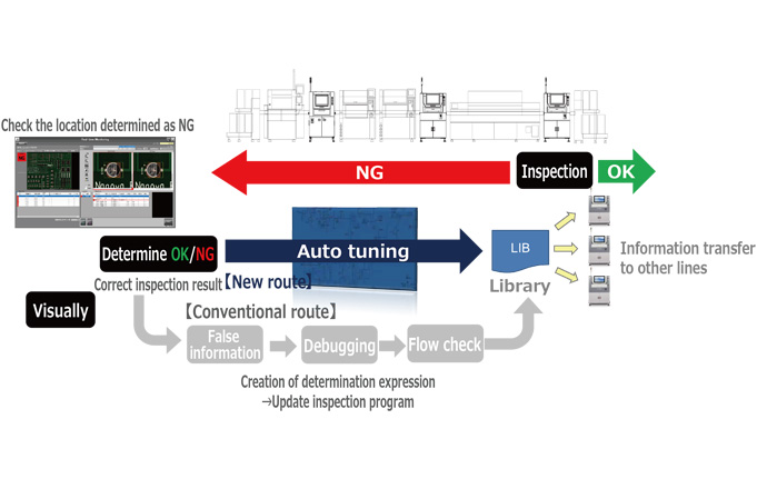
Significantly reduces the workload associated with false alarm countermeasures
By activating the newly developed “ZERO-SYSTEM”, tuning operations (e.g., re-setting of inspection thresholds) after visual check can be performed automatically. The system solves problems such as poor first-pass yield rate due to forgotten tuning operations, and high man-hours for tuning operations.
03 Solutions
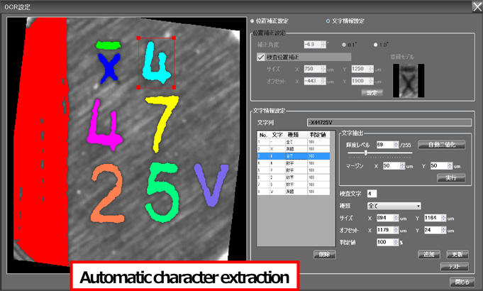
Character inspection
In addition to OCR, OCV is also supported. The system can use these functions on a per-character basis.
– OCR provides character recognition with excellent robustness.
– OCV provides versatility to handle special fonts and symbols.

Foreign material inspection
The large field of view size of 67.5mm x 67.5mm enables efficient inspection of foreign matters anywhere on the board.
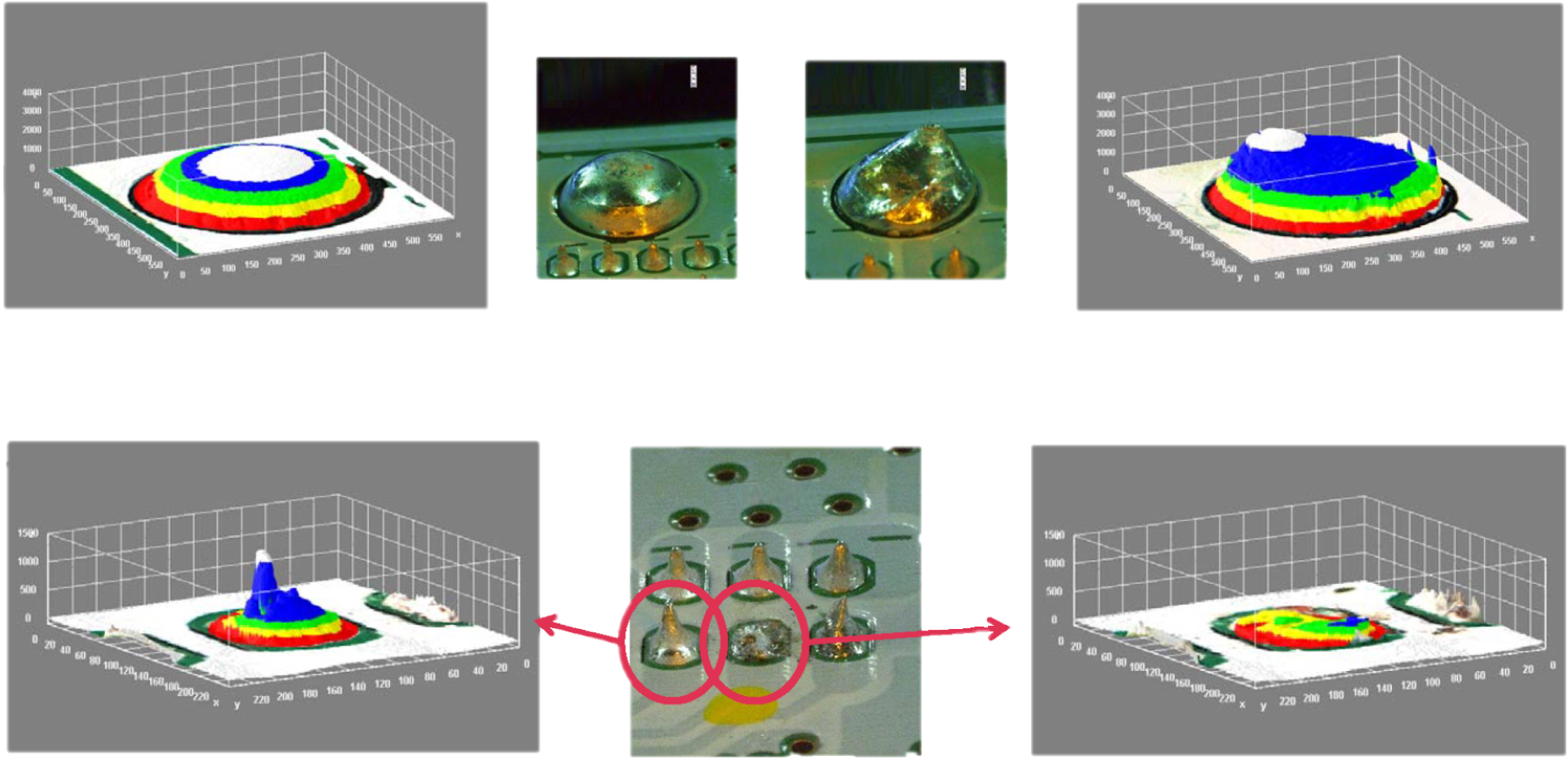
Wave soldering inspection
In addition to inspection of solder fillets formed by reflow soldering, inspection of soldered areas such as leaded parts formed by wave soldering is also possible.
Specifications
| PCB size | 50 x 50mm ~ 510 x 460mm | |
|---|---|---|
| PCB thickness | 0.4 ~ 6.0mm | |
| Transfer reference | Front rail, upper surface of PCB Transfer clearance: Upper 50 mm, Lower 50 mm | |
| Convey direction | Left to right, right to left, or return back (factory setting) | |
| Lane | Single | |
| Min. inspectable component | 0402(mm) chip component or equivalent | |
| Inspection lighting | 4-directional projector, top episcopic lihting, bottom RGB lighting | |
| Camera | 25Mpixcel camera with telecentric lens | |
| Resolution | 15µm | |
| Operation type | Key operation | |
| External dimensions | W1,120mm x D1,500mm x H1,500mm (excluding signal tower) | |
| Weight | 800kg | |
| Air supply | 0.3Mpa | |
| Power supply voltage | Single phase AC200 ~ 230V +/-10%、2kVA | |
| Option | 4-directional oblique cameras (factory setting) Center backup mechanism (factory setting) Pre-reflow spec Offline programming station Offline rework station Data storage server Smart Tuning System Easy Set-Up II | |